Interactive Digital Photomontage
Seldom does a photograph record what we perceive with our eyes. Often, the scene captured in a photo is quite unexpected — and disappointing — compared to what we believe we have seen. A common example is catching someone with their eyes closed: we almost never consciously perceive an eye blink, and yet, there it is in the photo — “the camera never lies.” Our higher cognitive functions constantly mediate our perceptions so that in photography, very often, what you get is decidedly not what you perceive. “What you get,” generally speaking, is a frozen moment in time, whereas “what you perceive” is some time- and spatially-filtered version of the evolving scene. In this work, we look at how digital photography can be used to create photographic images that more accurately convey our subjective impressions—or go beyond them, providing visualizations or a greater degree of artistic expression. Our approach is to utilize multiple photos of a scene, taken with a digital camera, in which some aspect of the scene or camera parameters varies with each photo. These photographs are then pieced together, via an interactive system, to create a single photograph that better conveys the photographer’s subjective perception of the scene. We call this process digital photomontage, after the traditional process
of combining parts of a variety of photographs to form a composite picture, known as photomontage.
We encourage you to view the video as an introduction to the framework. The paper is also a helpful guide for the types of effect possible.
Interaction Paradigms
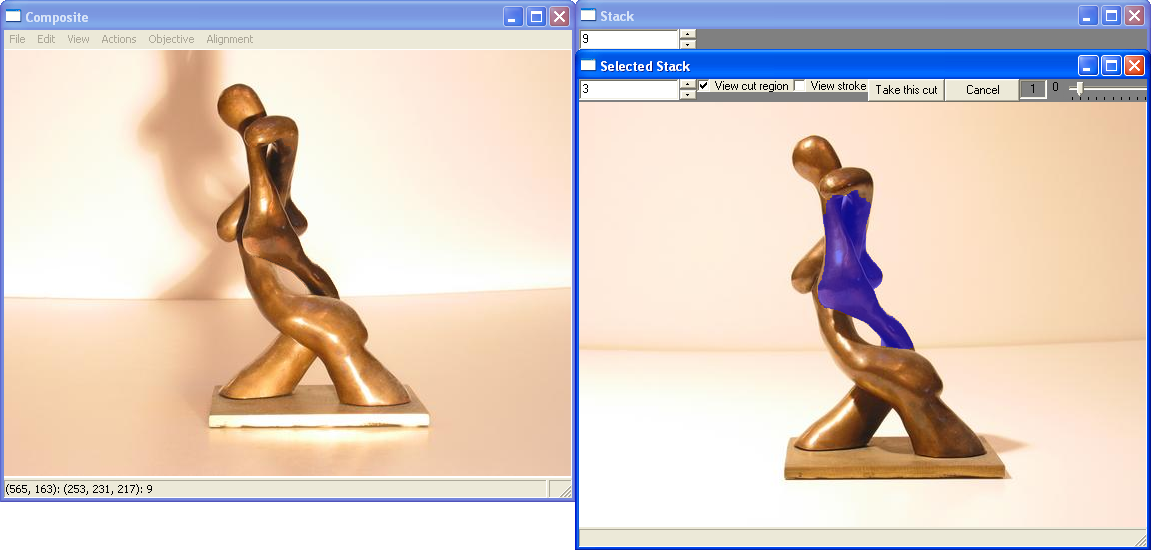
The user usually works with two windows: the composite window and the source window. The composite window, on the left, shows the current composite and the source window, on the right, shows the set of images that can be combined to form the composite. The user can scroll through the set of images using the number dial in the source window. For most applications the order of the images in the source window is of no consequence.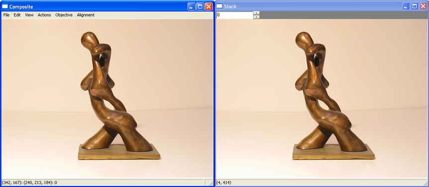
The user can form the composite using a series of objectives. The types of objectives currently in the framework include color, max/min luminance, max/min likelihood, max/min contrast, etc. These objectives can be applied globally to the whole composite, such as when one wants to create an extended depth-of-field image from a set of images with different focal lengths. Or they can be applied locally through a painting style interface. The user paints with rough brush strokes and the framework is able to combine the desired characteristics into the composite as seamlessly as possible. For specific examples, please look through the tutorials. When interacting with the composite locally through painting, the user can paint with one of two brushes, the single-image brush and the multi-image brush.
Single-image Brush
With the single-image brush the user wishes to add just one image to the current composite, and that that image should be the best one that both satisfies the objective under the stroke as well as fits with the existing composite as seamlessly as possible. To provide the user control over the choice of this best image, immediately after painting the user is shown a third window, called the selection window.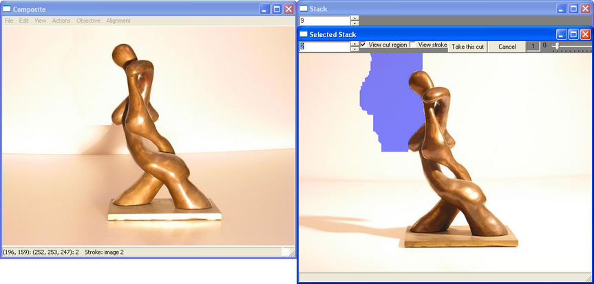
The selection window provides a set of images that best fit the specificied objective under the stroke. Each image has a region masked in blue which specifies the cut that would be included in the composite if the user was to choose that image. In the visualization above, the user is viewing the 3rd best image while trying to eliminate a shadow on the wall. The composite window shows how that blue region fits with the existing composite. The user can scroll through all the potential cuts and pick one (the cut is already computed) or refine it by painting additional strokes.
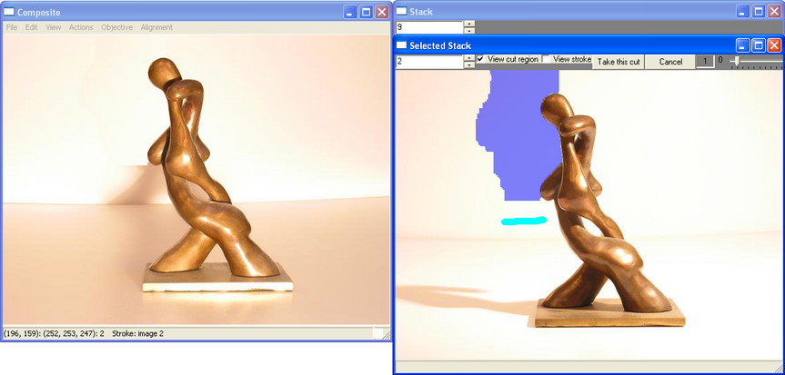
The additional strokes remove the whole shadow.
Once the user is satisfied, he can accept this new addition to the composite with the "Take this cut button" or reject it and start over again.
Multi-image Brush
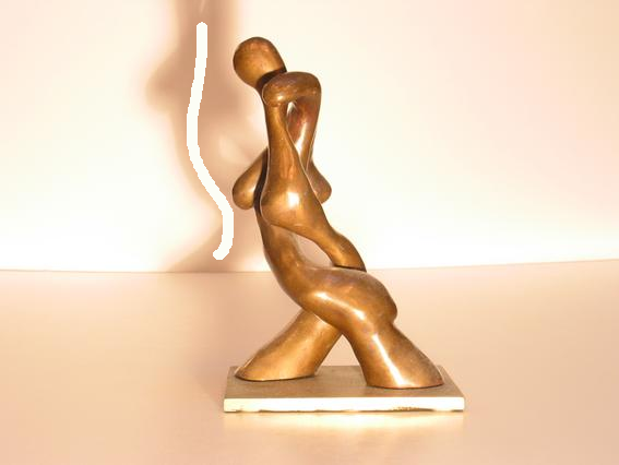
The multi-image brush is useful when one image does not include all the required effects. As an example, to create the halo around the subject's head, we used just one stroke of the multi-image brush . In such cases the framework proceeds as if a global objective had been specified: all possible source images are fused together in order to best meet the requirements of the locally-specified image objective, in this case the max luminance objective. However, this operation can take significant time to compute.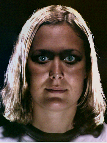
Description of Menus
Composite Window
- File
- New Composite … – Loads first image to represent composite (loads only one image, not full stack).
- Load Stack … – Loads the whole stack (select all images that are part of image stack) The composite loaded will always be the first image in the stack. If the composite image was one of the images selected for the stack, that image will be included in the stack only once.
- Load Labeling … – Loads the labeling of a previously created composite. In order to result in the same previously created composite, one must load the original composite and stack in the order it was done originally.
- Save Image … – Saves the image that is currently displayed in the Composite Window.
- Save Composite … –Saves the graph-cut composite image (this is the image you see when you select View->Simple Composite).
- Save Gradient Composite … – Saves the gradient composite image – after merging in the gradient domain (this is the image you see when you select View->Gradient Composite).
- Save Labeling
… – Saves the labeling used to produce the
composite image.
Applications:
There are a number of constants associated with the graph-cut computation, such as ones that change the importance of the data penalty or interaction penalty. For different applications, different values are appropriate. We have preset the constants for some of the most common applications. For others you can start with the default constant settings and alter them through the View->Constants menu if necessary.
- Default
- Group Portrait – select when fixing up group portrait (see tutorial I for example).
- Face Merging - select when merging facial features.
- Background Reconstruction – select when removing foreground elements and reconstructing the background.
- Extended Depth-of-field– select when creating an extended depth-of-field composite.
- Exit– exits application.
- Edit
- Undo – undo the last operation.
- Brush: Erase Stroke – use this brush to erase parts of strokes. Make sure to be viewing the strokes when erasing them (View->Overlay Strokes).
- Clear All Strokes – clears all strokes and resets the composite to the original (first loaded) image.
- View
- Constants – These constants are used to control the graph-cut optimization. For further information email us – these probably won’t be in the final version.
- Simple Composite (a) – view composite created by copying pixels as dictated by the labeling computed by the graph-cut optimization.
- Gradient Composite (f) – view composite created by copying gradients as dictated by the labeling computed by the graph-cut optimization and then integrating the gradient field. This technique is useful when a seamless combination is impossible, such as due to skin tone differences in the facial feature merger application. Must compute this composite first (Actions->Compute Objective Globally)
- Overlay Labeling (s) – overlay labeling on top of simple composite. The labeling is color coded with the source images. Each color represents a different source image. If you scroll over the labeling, the source image number is displayed in the status bar.
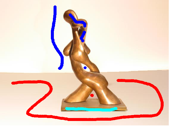
- Overlay Strokes (x) – overlay strokes on top of simple composite. The strokes are color coded with the source images. Each color represents a different source image.
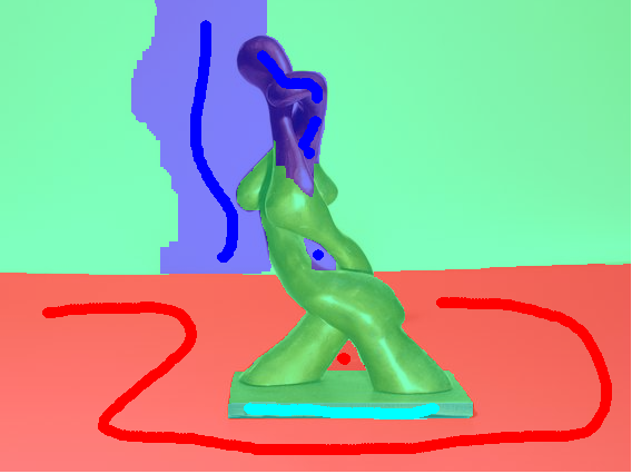
- Labeling
and Strokes (d) – overlay labeling and strokes. The
labeling and strokes are color coded with the source images. Each color
represents a different source image.
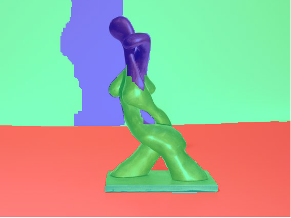
Overlay Labeling
Overlay Strokes
Overlay Labeling and Strokes
- Actions
- Compute Objective Globally – select to compute objective globally for the whole image instead of locally through brushing.
- Set All Labels to Current Image – set the composite to the image currently displayed in the stack viewer.
- Add Composite To Stack – make the current composite part of the stack.
- Recompute Composite – recompute the labeling with the graph-cut optimization.
- Fast Blend – creates an integrated gradient composite, uses original Poisson editing technique (can be sufficient for some applications). All outer edges of composite must be labelled 0.
- Quality Blend – creates an integrated gradient composite, uses refined integration technique w/ discontinuities and boundary constraints.
- Objective
All objectives are per pixel heuristics that can be used to create certain effects such as creating or eliminating highlights and shadows, or reconstructing the background in a scene with transient foreground objects. The objectives can be run globally across the whole composite or they can be applied locally to a specific region in the composite. Often times the user can iterate and use different objectives for different purposes in creating the composite. Please see video and tutorials for examples.
- Source – specifies a designated source from the stack of images. Use this objective to make the source in the composite a specific image from the stack. (see Group Portrait tutorial)
- Color – specifies a desired color to match or avoid. The desired color is shown in the lower right. There are two ways to select this color. One is to shift-click anywhere in the composite view; this selects the color under the cursor. Another approach is to click with the right mouse button to bring up a palate
showing all the possible colors for the pixel under the mouse. Then
select the desired color and paint with it to specify which region
should be in that color. This objective can be useful for removing
highlights and shadows.
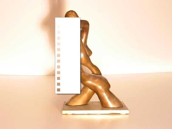

color pallate lists possible colors
brush stroke with specified color
the shadow on the wall is remove
- Max/Min
Luminance – specifies the brightest/darkest pixels
from those possible for that pixel in the set of images. If run
globally this objective will bring out
all the possible highlights/shadows from the set of images. If used
locally with a brushstroke, it can add a highlight/shadow to a specific
region.

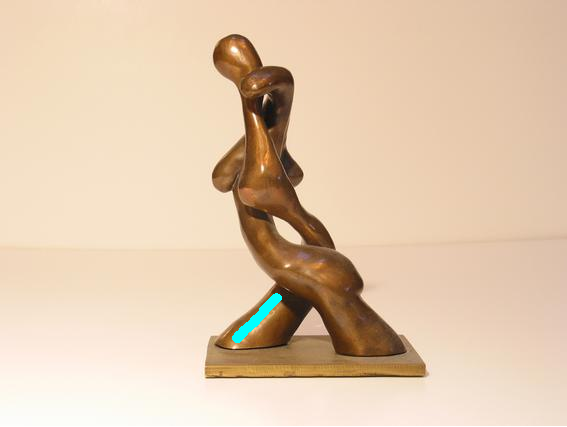

global max luminance
local brush stroke
local max luminance
- Max/Min Likelihood – specifies colors of pixels that appear most/least often at a certain position in the composite. If run globally the max likelihood objective can be used for background reconstruction by removing transient foreground moving objects. The min likelihood objective can be used for creating crowds.
- Max/Min Contrast – specifes pixels with most/least contrast in a local neighborhood. The max contrast objective is used to create extended depth-of-field images, while the min contrast objective can be used for background reconstruction.
- Max Difference – specifies pixels that are maximally different from a pre-specified image or region of the composite. This objective is used to create stroboscopic effects. First a background image is created with the maximum likelihood objective and then the max difference objective is run globally with respect to the background reconstruction.
- Timelapse– specifies that the source images in the composite should vary from left to right with the order of the images in the stack. For this objective there is an implicit assumption that the stack of images is ordered in some meaningful way.
- Panorama – is used to remove ghosts and distracting artifacts from panorama images. Please ask for details on image format.
- Difference – similar to the maximum difference objective however different in that it picks pixels that are different from the current composite not a specified image.
- Alignment
The alignment operators are useful for manual and semi-automatic image registration. Some of our application assume preregistered images. If the images are not registered, they can be registered with some of the following operators. Usually the original image in the composite view is not transformed. As the user wants to add new images to the composite they display them in the stack view, overlay them in the composite view and align them. As the image is scaled in the composite window, the transformation can also be viewed in the stack window.
- Overlay Stack
Image - display a half opaque version of current image in stack
viewer on top of current composite in the composite viewer. This is
useful for manual alignment
- Translate - translates overlapping image with left mouse button dragging.
- Rotate - rotates overlapping image with left mouse button. The center of rotation is the center of the composite window.
- Scale - scales overlapping image with left mouse button dragging.
- Points- allows the user to specify three points both in the composite and source view that should be aligned. Each of the three point pairs must be input first in the composite view and then in the source view. After inputing three source pairs, the source image will be warped to align the points.
Source Window
- Number scroll - allows scrolling through set of images.
Selection Window
- Number scroll - allows
scrolling through the set of selected images
and their computed cuts.
- View Cut Region - shows
the region that will be cut into
composite if current image is chosen. Region is marked in blue.
- View Stroke - show the
strokes that generated the regions to be
cut into the composite window.
- Take This Cut - accept
the currently viewed image and its
corresponding cut as the one to be added to the composite.
- Cancel - cancel this
stroke.
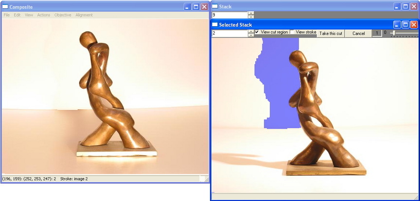
- Inertial Scroll Bar -
The inertia parameter allows the user to
specify that only pixels close to the brush stroke should be affected
by the stroke. The higher the inertia setting, the smaller the region
of the source image that is automatically selected. The example
below shows how the source cut region (marked in blue) shrinks with the
increse in inertia.

inertial setting: 1
inertia setting: 3