The system has been written to make the surface match with all the constraints and keep the same surface as smooth as possible. Discontinuities are therefore totally excluded from any results, since the idea of discontinuity itself is the total opposite of what the smoothness of a surface can be. That's the reason why discontinuity should be specify to the solver, differently from the constraints. Two types of discontinuities can be defined. both of them are quite easy to apprehend :
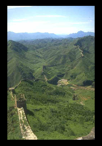
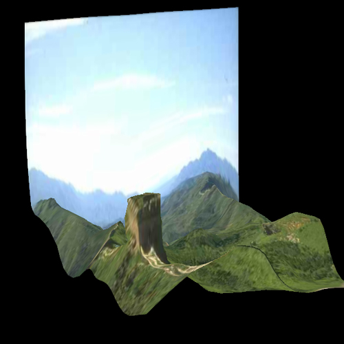
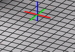
Setting the constraints allow the user to give the model a shape. It is however generally impossible to build a model from a simple plane, especially because most of images are separated into different layers. For a close-up, the object is divided from the background ; it is all the more true for a landscape, where the depth field is far larger. The Position discontinuity tool can fix this problem and place the differents layers.
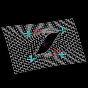
Adding a Position discontinuity is fully equivalent with cutting the surface with a pair of cissors.
 How do Position discontinuities work ? First, the user has to draw a following of segments and indicate theit state – position discontinuity. The engine gets rid of all the cells that are cut by the discontinuity ; they aren't drawn any more, and are not involved in the solver. The contour the user has drawn was only an indication for the solver : the real discontinuity is in fact delimited by the cells that have disappeared. The cells are squares however, and to avoid too much aliasing along the discontinuity, the system increase the resolution up to maximum – that will be adjustable by the user – in order to limitate this aliasing.
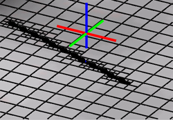
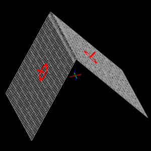
The system tends to build a model as smooth as possible. As the position discontinuity needed to be treated separatly from normal zones, normal discontinuity need also. Through a normal discontinuity, the surface remains continuous, but there is no dependancy between the local slope of the two parts, in the direction orthogonal to the discontinuity :
Adding a normal discontinuity is locally equivalent with bending the grid, like a sheet of paper, along the segment.
 How does normal discontinuity work ? This time, we cannot get rid of cells, since the surface is continuous. The only think that can be done is remove some smoothness along the discontinuity – see Technical explanations for more details. The resolution is also automatically adjusted to remove aliasing along the curve
![]() Position and normal discontinuities are created, modified and removed in the same way
Position and normal discontinuities are created, modified and removed in the same way![]()
 |
To set a discontinuity, switch to the New Mode and select the Position/Normal discontinuity option. The curve you can currently draw are only piece-wise linear curve : just click on each point you want to set on the left side of the window. While you are creating those points, the discontinuity is not dynamically included in the solver : you have to end the curve to validate it. |
|
To end the curve, press Enter : this will add the last point at the current mouse position and end the curve. |
| While trying to end the curve, if you move the cursor over the first point of the same curve, the latter will be highlighted : if you press enter while highlighted, you will create a closed curve. In the future version, this will be simplified. | |
|
To move a discontinuity, just click on the point to select it, then drag it to move it. |
|
To delete some key points in the curve, click on the point to select it, then press Backspace to remove it |
|
To remove the whole curve, select it and press Delete. |
  |
WARNING : You have the possibility to stop the solver before moving around the discontinuities. I don't advise you to do so : if you modify or add some constraints before releasing the solver, the system will crash !!! |