|
"Position constraint" option
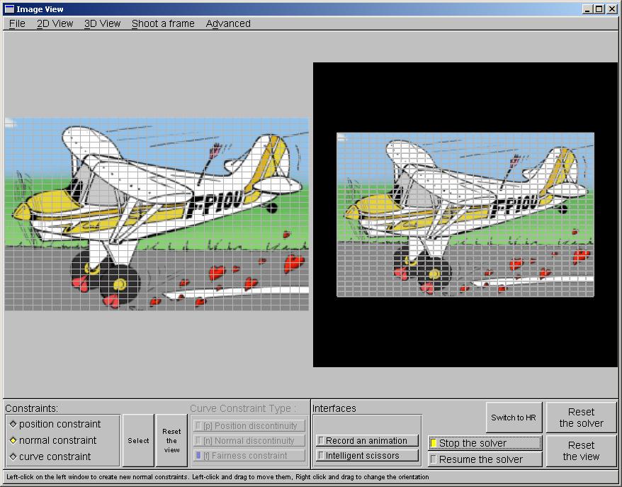
When this mode is activated, you can add position constraints on the model.
A position constraint will fix the height of a point in the model.
- Left-click on the left view to create a position constraint
- Left-click on a constraint to select it. When you move over a constraint or when you select it, it's color changes.
- Left-click and drag to adjust the position of the constraint in the image
- Right-click and drag to adjust the height of the constraint.
- Press Delete to remove the currently selected constraint
- Use Tab and Shift-tab to select the next/previous constraint
|
|
"Normal constraint" option
When this mode is activated, you can add normal constraints on the model.
A position constraint will fix the local orientation of the surface model.
- Left-click on the left view to create a normalconstraint.
- Left-click on a constraint to select it. When you move over a constraint or when you select it, it's color changes.
- Left-click and drag to adjust the position of the constraint in the image.
- Right-click and drag to adjust the orientation of the constraint.
- Press Delete to remove the currently selected constraint.
- Use Tab and Shift-tab to select the next/previous constraint.
|
|
"Curve constraint" option
When this mode is activated, you can now choose between three different curve constraint type :
Position discontinuity, Normal discontinuity and Fairness constraint. These curves have different meanings,
but the interface works the same way
- Left-click on the left view to start creating a piece-wise linear curve.
- Left-click on the left view to go on adding some key points to the curve.
- Press Escape to cancel the creation of the current curve.
- Press Enter to validate the curve. The position of the mouse will be indicate the position of the last point.
- Left-click on a key-point of a curve to select the curve and the key-point in the curve.
- Press Delete to delete the selected curve.
- Press Backspace to delete the selected key-point in the selected curve.
- Left-click and drag on a key point to move this key-point.
- Right-click and drag on a key point to make the curve interface pop-up.
- Middle-click on a key point to change the type of a curve, after having selected the Curve Constraint Type you want.
|
|
"Curve constraint Type" options
You can only select the Curve constraint type if the Curve constraint option is selected
- Position discontinuity
Adding a position discontinuity will cause a cut in the model. This feature is used to handle depth discontinuities.
- Normal discontinuity
Adding a Normal discontinuity will create a sharp edge in the model. This feature may be used to handle geometric forms with edges.
- Fairing Curve
Adding a Fairing constraint will smoothen the model along the curve. Use the Curve Interface to change the parameters of a Fairing constraint.
|
|
Curve Interface
You can make it pop-up buy right-clicking on a key point of a curve, the Curve Constraint option is selected
You can chose to close the contour or not.
If it is a fairing curve, you can specify curvature weights - to smoothen the curvature along the curve - and torsion weights - to smoothen the torsion along the curve.
If it is a position discontinuity, you can add constraints automatically along the curve to simulate a silhouette effect.
Specify the distance between the constraints using the slider, and the angle to set the normal orientation to the curve.
Warning : these automatically added constraints are separate from the other ones... If you move the curve, the auto-bump constraints will move also
If you want to modify them as normal constraints, you have to export them first, using the "Export constraint" button.
|
|
"Select button"
With this tool, you can change the grid resolution if needed. Press the "Select" button to activate the tool, left-click and drag to select the region where you want to change the resolution, then press + or -, without shift, to change the resolution.
Notice that adding a position discontinuity will automatically change the resolution to avoid aliasing, but these adjustments are always done after, so don't worry about it when you change the resolution.
Press the "Select" button again to be able to modify the rest of the model again
|
|
"Switch to HR" button
Use this button to get the highest resolution to get a smooth model. This feature is useful is finished and when you only want a result, since the model computation is slow when this High-resolution mode is activated.
|